13 KiB
TERES-I Assembly
Table of Contents
- Preparation
- Included Materials
- Touchpad
- Touchpad Buttons
- Microphone
- Power Buton
- Mainboard
- Cabling
- Speakers
- Body Panels
- Camera
- WiFi
- More Cabling
- Magnet
- Battery
- FInal Steps
Preparation
First, prepare a workspace with enough room and light to assemble the laptop. Cover the workspace with soft material to prevent scratching the laptop's plastic parts. Ideally use a grounded electronics mat. Read and follow the instructions carefully and do not rush! Disassembling the finished unit to fix earlier mistakes is considerably harder than assembling the unit!
Included Materials
Touchpad
The assembly process begins with the TERES-006-Keyboard:
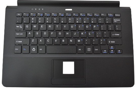

First attach the touchpad TERES-023-Touch to the keyboard's body:
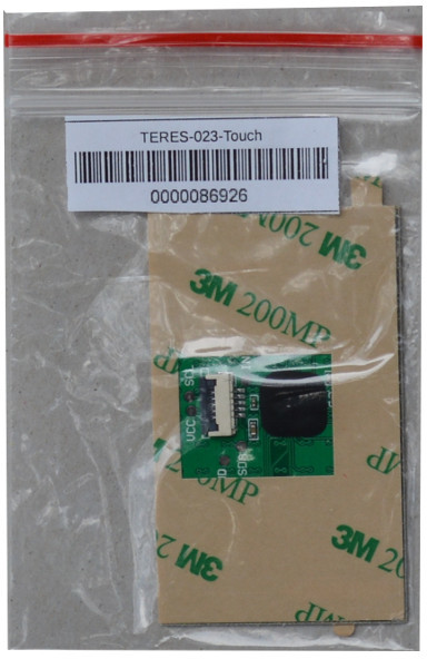
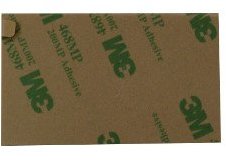
The touchpad uses double sided adhesive tape. Remove the protective foil and place it on the top side of the keyboard body like shown in the pictures below:

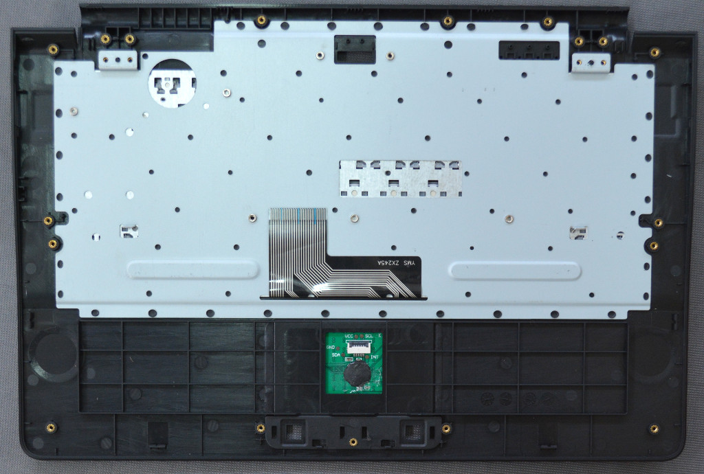
Be careful to place the touchpad connector so that it faces the correct way! The exposed pins of the connector must be pointing up.
The touchpad snaps tightly to the upper side plastic. You should place the pastic cover on an even surface and make sure the touchpad connector is fully inserted.
Next, turn over the cover and place TERES-022-Touch-Cover and TERES-010-Touch-Btns on top of the touchpad:


The final result looks like this:

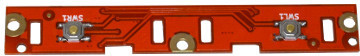
Touchpad Buttons
The next step is to attach the TERES printed circuit boards to the keyboard body. For this purpose use the TERES-014-Screw-Set. Note that in this set there are 42 screws of different lengths:
- M2 x 1.5 ( 4 pcs)
- M2 x 3 ( 9 pcs)
- M2 x 4 (17 pcs)
- M2 x 5 (12 pcs)
It is a good practice to:
- Sort all the screws before you begin, as each screw must be placed in a specific location based on length
- Do not mix the lengths of the screws during installation; doing so may damage the plastic parts
- Be gentle! Do not torque the srews as tight as possible; this may break the plastic
All screws have same diameter (M2), but different lengths. Use a metric ruler if you have difficulties determining the length. For example, the M2 x 5 screw would have 5mm thread length (i.e. not including the head).
For the PCBs the M2 x 3 screws must be used.
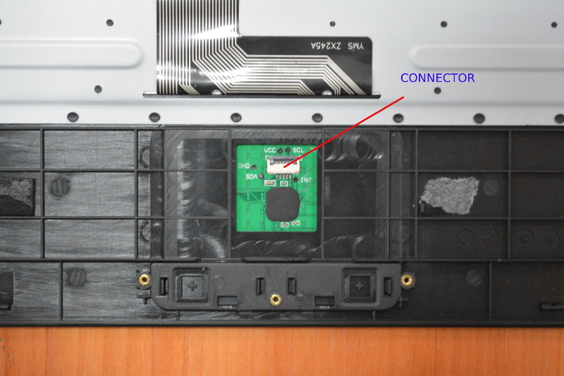
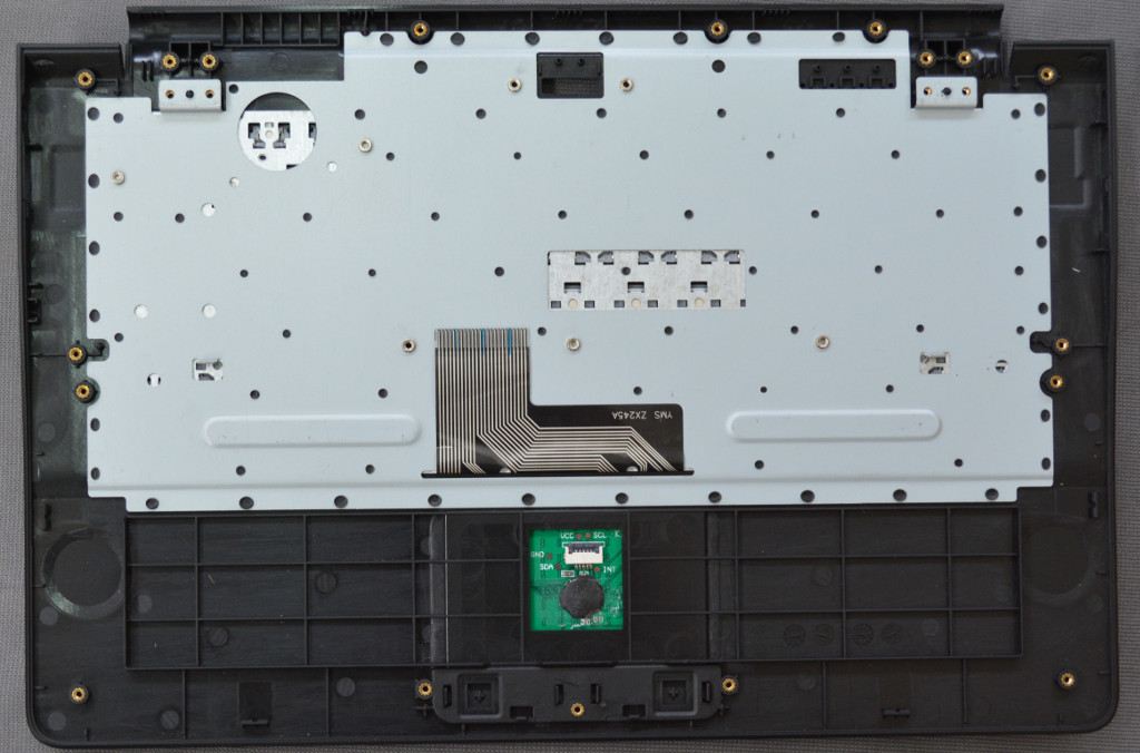
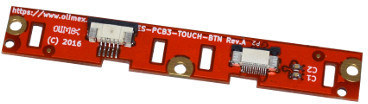
Now we assemble the TERES-PCB3-Touch PCB:
It is shown below, attached to the keyboard body. Note that only the middle screw is used. The other two screws will later be used when fixing the bottom plastic cover:
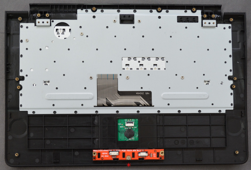
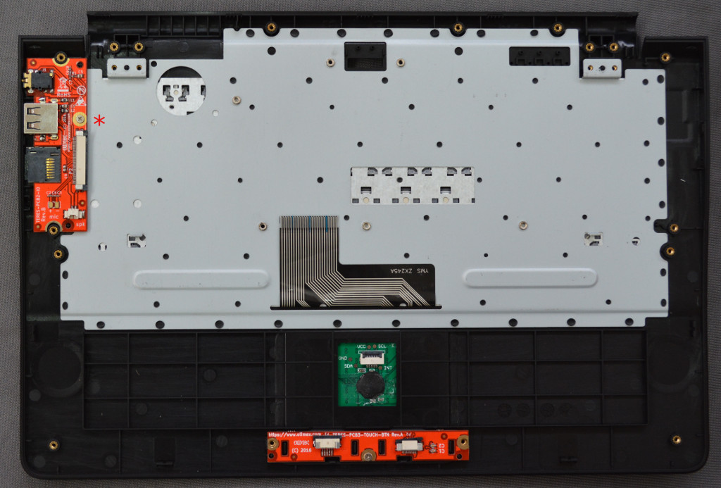
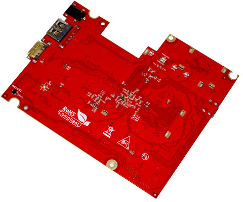
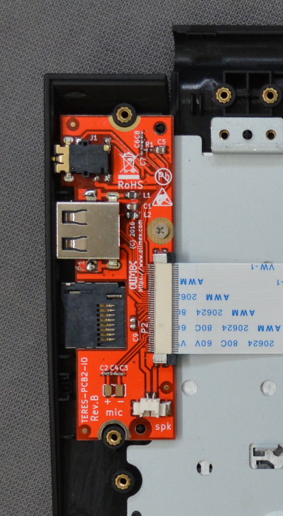
The next PCB to attach is the TERES-PCB2-IO:
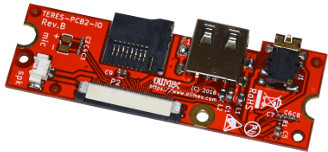
The PCB2 board has a microphone which has to be placed in the side pocket specially designated for it.
Microphone
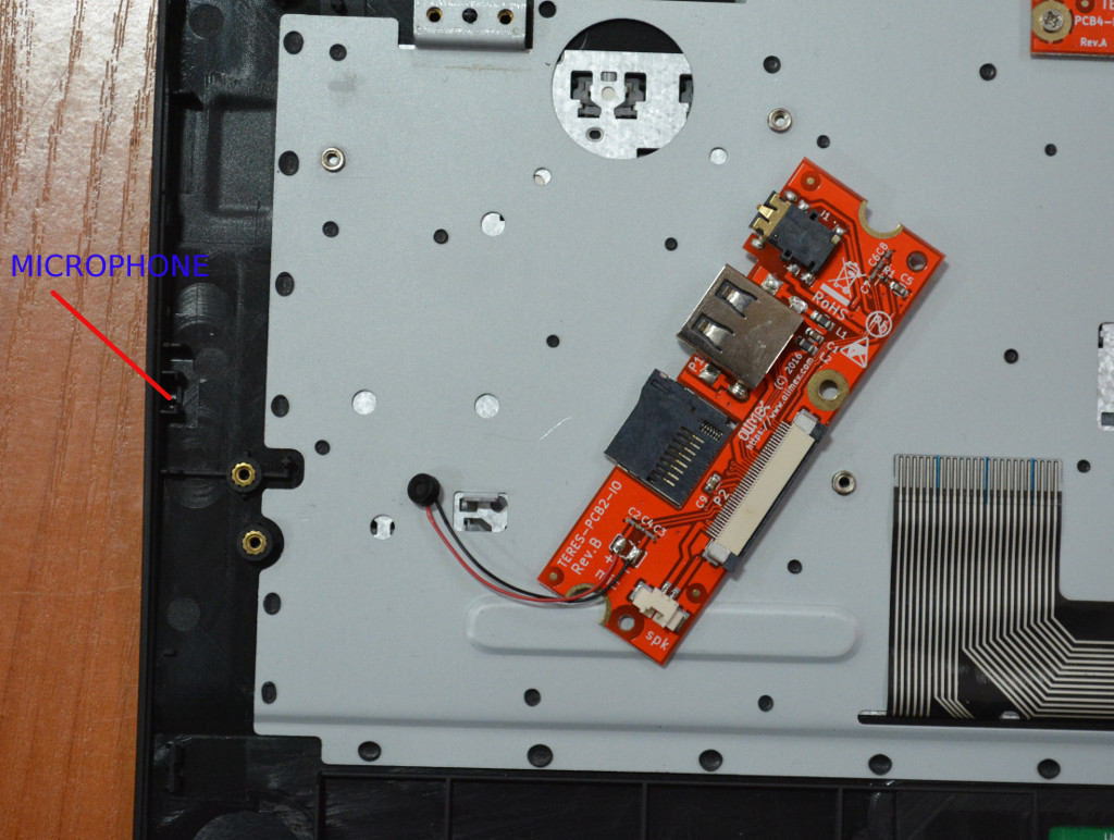
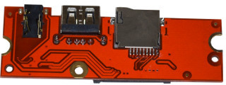
After the microphone is put in place, slip the board at an angle into the side openings for the SD card, USB, and audio connector, then place it down.

Then use one M2 x 3 screw to fix the board:
Please make sure that the side connectors are well aligned:

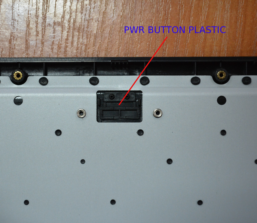
Power Button
Next you put the PWR button plastic:

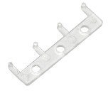
Then the LED pipe:
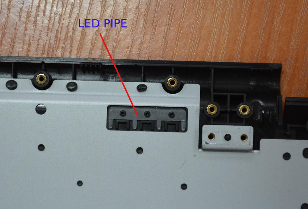
Next attach the TERES-PCB4-Btn (the power button):
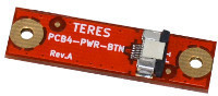
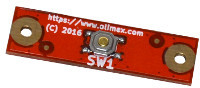
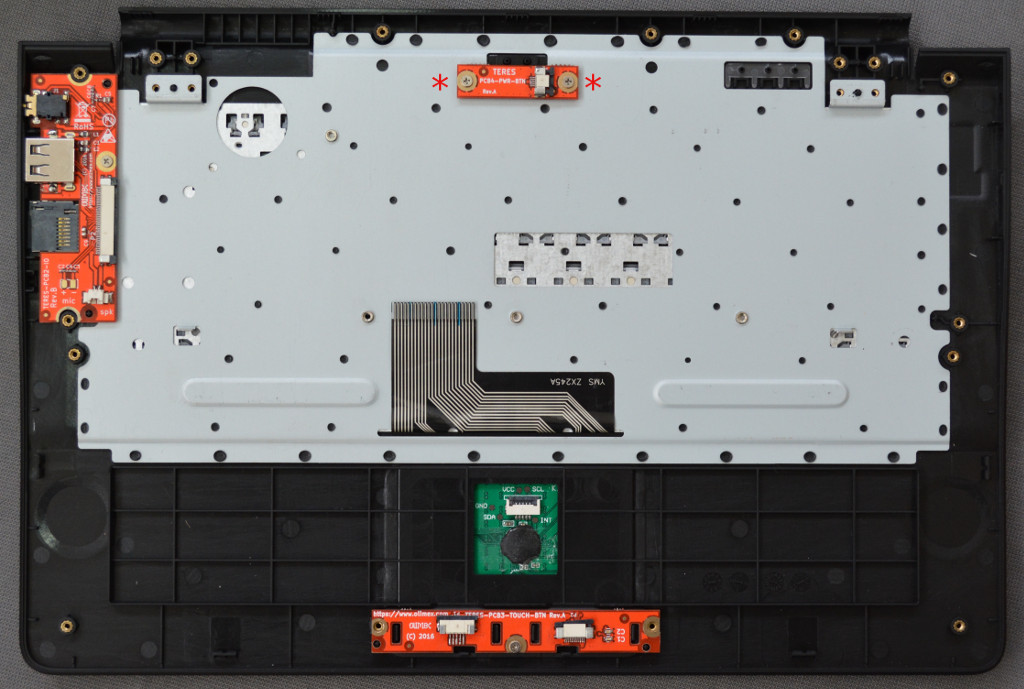
The TERES-PCB4-Btn is attached with two M2 x 3 screws with the connector pointing to the right side:
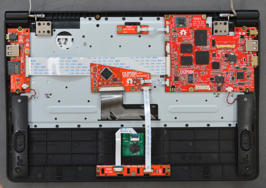
Mainboard
The next step is to assemble the big TERES-PCB1-A64:
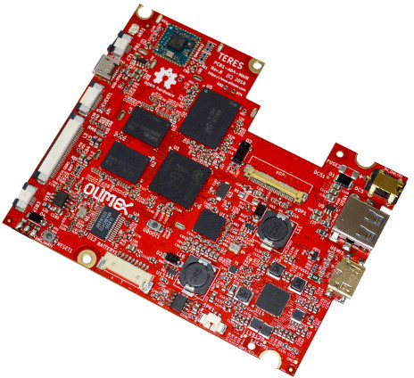
This is the main board and you should handle it very carefully. Do not bend it, do not drop it, etc. This board is very sensitive to static electricity; a grounding strap is recommended for use during handling.
It is a bit tricky to place the mainboard in the correct position as you must slide it in a way that the connectors enter properly in the plastic body side openings. If you succeed you will see all the PCB support nuts from the keyboard body pass exactly through the openings of the PCB. You need to use two M2 x 3 screws to attach it:

Again, ensure that the side connectors are properly aligned:
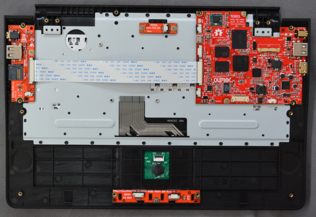
Cabling
Now connect TERES-PCB2-IO with TERES-PCB1-A64. For this purpose, use the Flat Cable TERES-027-FPC-IO-Main.

There are two 40-pin connectors on TERES-PCB2-IO and TERES-PCB1-A64. You have to open the latch – pull the dark plastic of the connector up and insert the FPC cable above it with the contacts up:

After you have inserted the cable, push the dark plastic back down so it locks the cable to the connector:
Repeat the same with the TERES-PCB1-A64. TERES-PCB2-IO and TERES-PCB1-A64 are now connected together:
Do the same for TERES-PCB4-Btn and TERES-PCB1-A64. Use the small flat cable TERES-028-FPC-Pwr-Main. These connectors are similar to the previous ones. You should again disengage the lock (pull the dark plastic up), then insert the flat cable with the contacts pointing UP between the white and dark plastic then push the dark plastic back. Here is the flat cable connected to both connectors:

The next step is to connect the touch panel TERES-023-Touch to the board with touch buttons TERES-PCB3-TOUCH. Use the flat cable TERES-029-FPC-Touch-Btn. Note that these connectors are different; the touch panel connector has a hinge and the dark plastic gets opened upside as on this picture:

The flat cable is also inserted with the contacts pointing down and blue back up:

The connector on TERES-PCB3-TOUCH is also different so the cable is inserted below the dark plastic again with blue back pointing up:
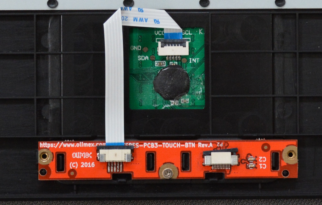
You have to bend the cable twice. Do not bend at a very sharp angle and don't bend it too hard, or else it might get damaged!
The next step is to attach the TERES-PCB5-KEYBOARD to the keyboard flat cable as shown on the picture below. Note that the cable goes under the black sliding plastic of the connector:
Do not assemble the keyboard PCB to the plastic base at this time.
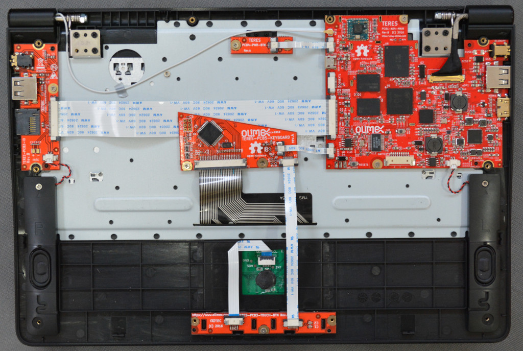
The next step is to connect TERES-PCB5-KEYBOARD with TERES-PCB3-TOUCH. Use the TERES-031-FPC-Kbd-Btn flat cable for this purpose. The cable is inserted with contacts up above the black plastic of the connector, in the same way as the power button and main board cables:


Next connect TERES-PCB5-KEYBOARD with TERES-PCB1-A64 and using one M2 x 3 screw attach TERES-PCB5-KEYBOARD to the plastic body. Note that only the left screw is placed. The right screw will be installed later when attaching the bottom plastic.
Speakers
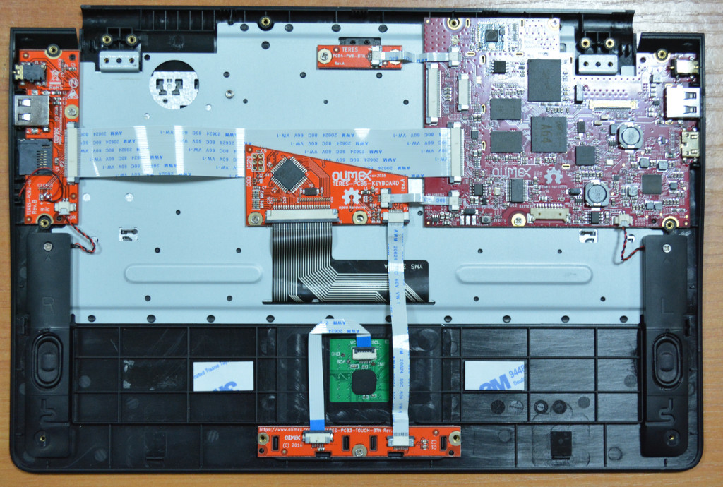
The final assembly step is to attach the left and right speakers. Look at the bottom side you will notice that right speaker is assembled at the left hand side, and the left speaker at the right hand side.
For this purpose use M2 x 4 screws and only screw in the upper one. The speaker connectors should be inserted in TERES-PCB2-IO and TERES-PCB1-A64 boards.
Body Panels
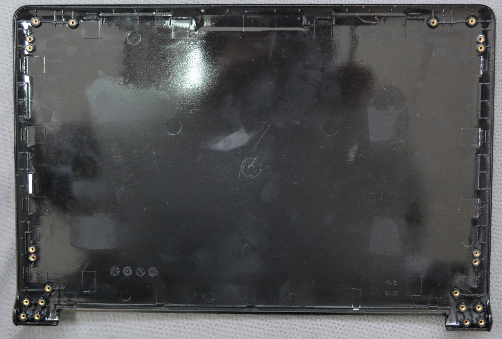
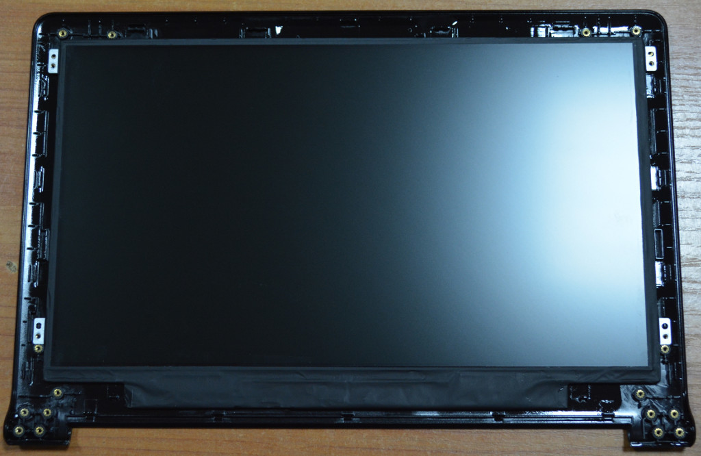
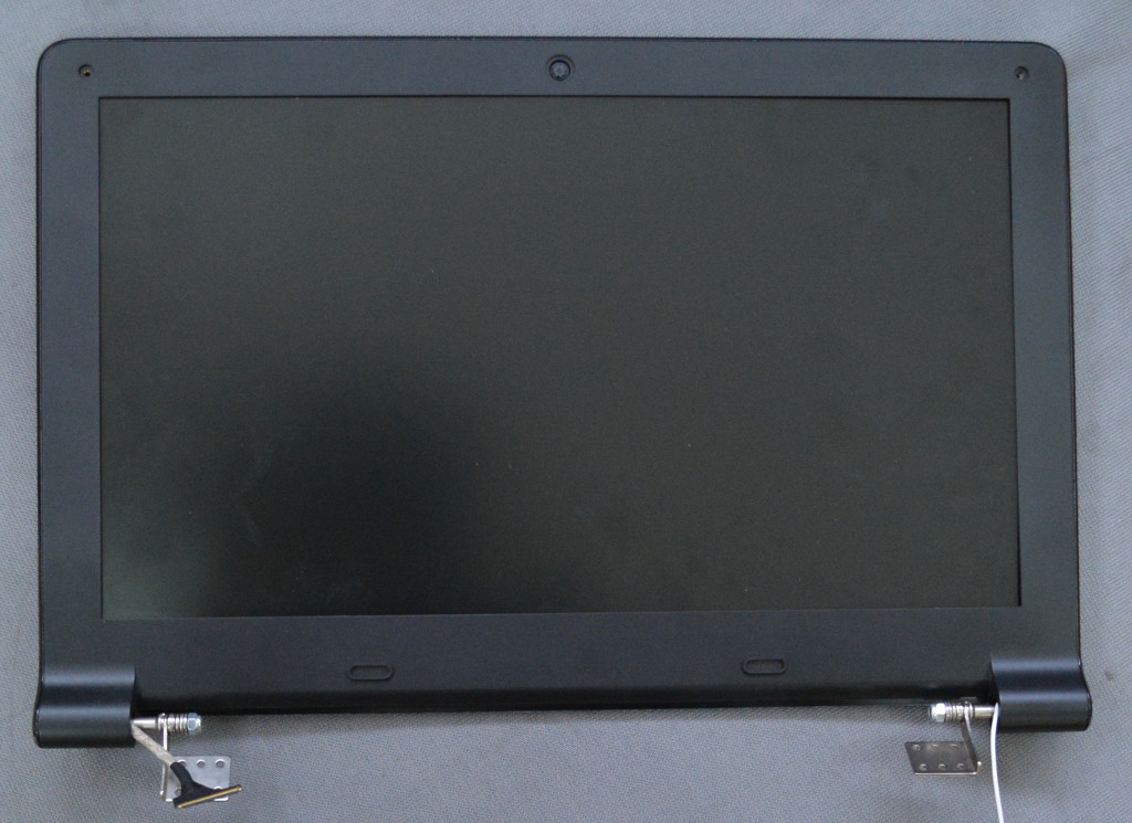
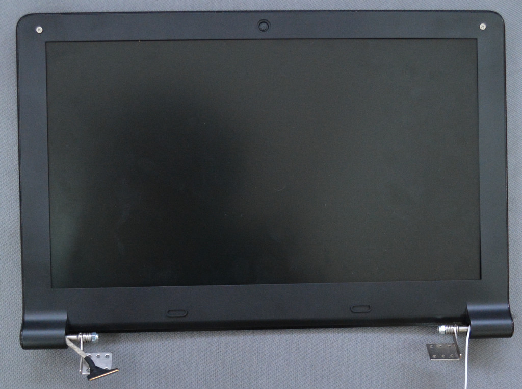
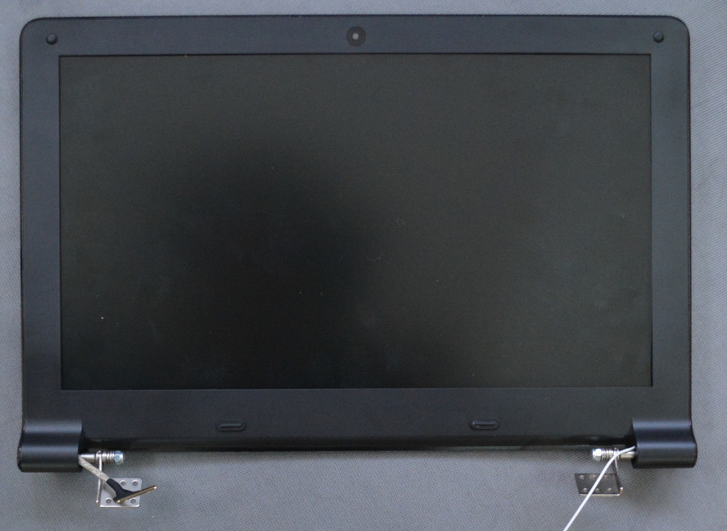
Now continue with LCD frame assembly using the TERES-008-LCD-Back as base:
First attach the metal hinges to the TERES-016-Hinge-Set using 8 pcs M2 x 4 screws:

Next attach TERES-026-LCD-cable to the TERES-015-LCD 11.6" panel (datasheet):
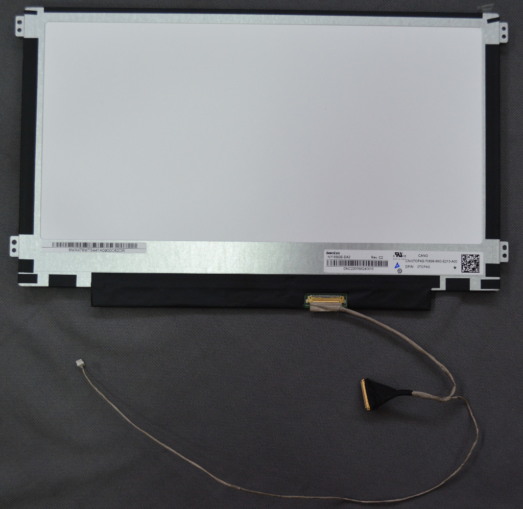
With M2 x 1.5 screws assemble the LCD to the plastic. Note that only 4 screws are used!
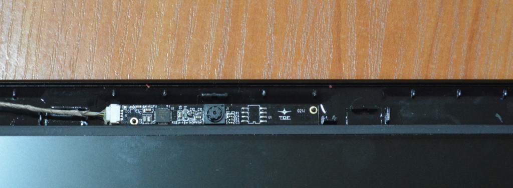
Camera
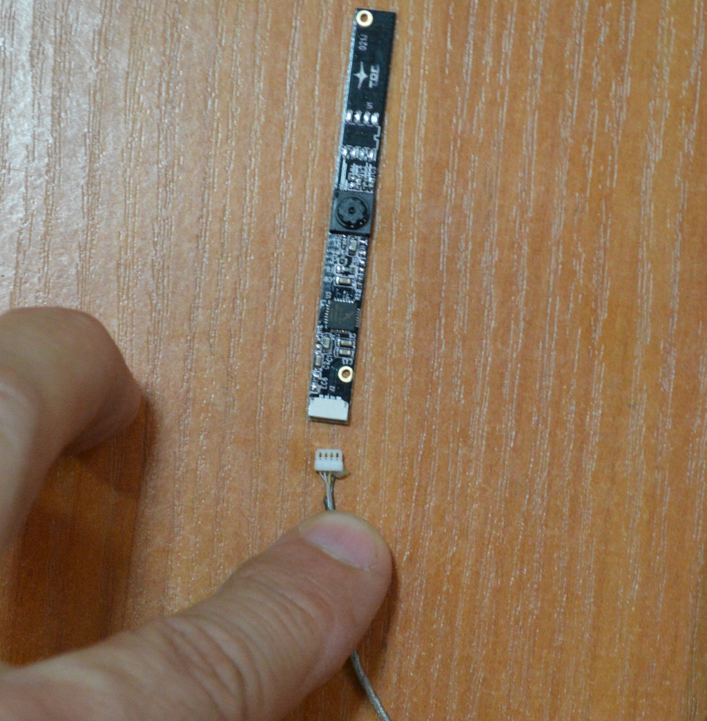
Connect the TERES-019-Camera to the four pin connector of the TERES-026-LCD-cable. There are two holes in the camera board which attach to two pins on the plastic body.
WiFi
On the other side attach TERES-025-WiFi-Antenna with double-sided adhesive tape to the plastic body:
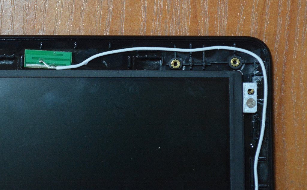
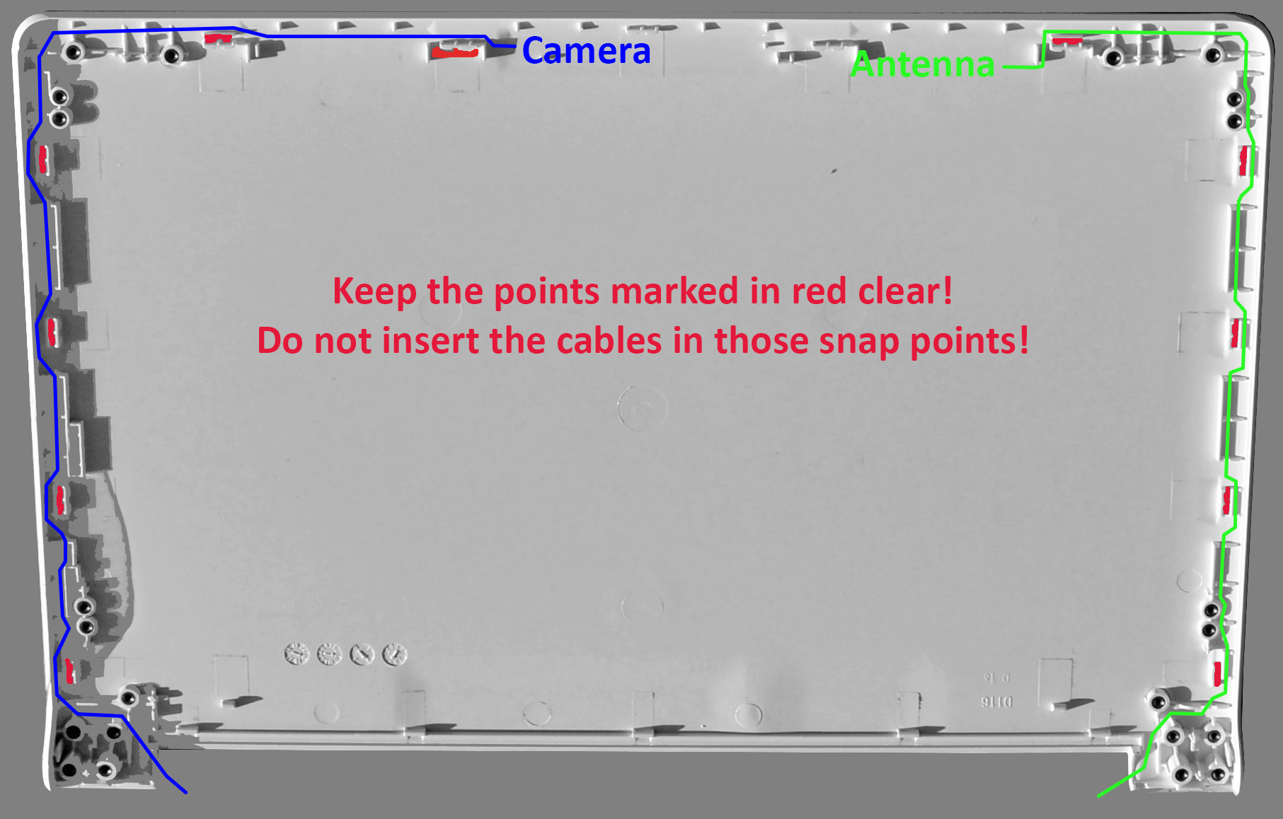
More Cabling
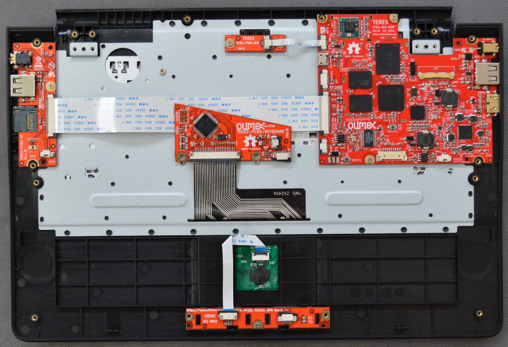
Follow the wiring shown on the picture below for the correct path of the LCD and WiFi cables. Pay attention on how the cables go around the plastic locks and hinges! The LCD cable wiring is probably most difficult part of the whole assembly and it is incredibly important to keep EXACTLY the same layout else the cover will NOT snap together properly later.
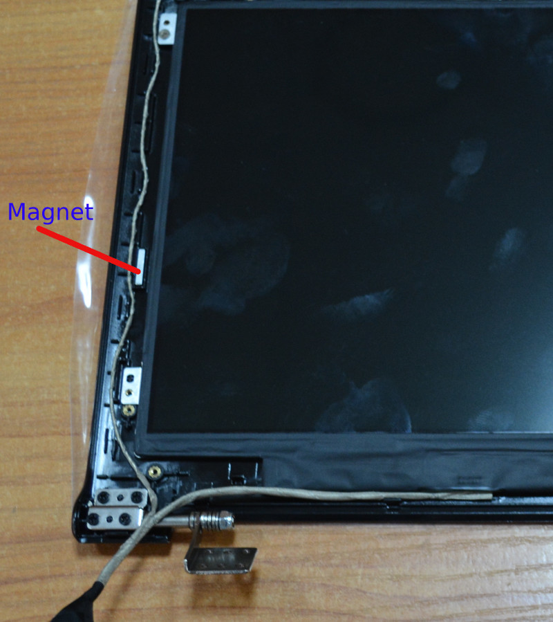
Magnet
The 018-Magnet is placed in special place on the left hand of the LCD:
Now place the panel. If you did the wiring correctly, the panel will snap tightly. You will have something like this:
If the panel doesn't snap properly and you have to remove the cover to re-do the wiring, please, be patient else the plastic locks can break. You can use a credit card or other similar card as a lever to separate the bottom and top parts of the display.
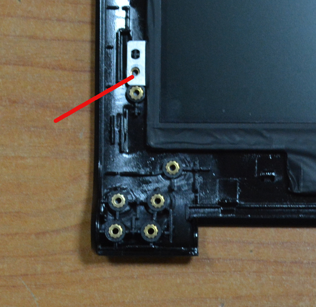
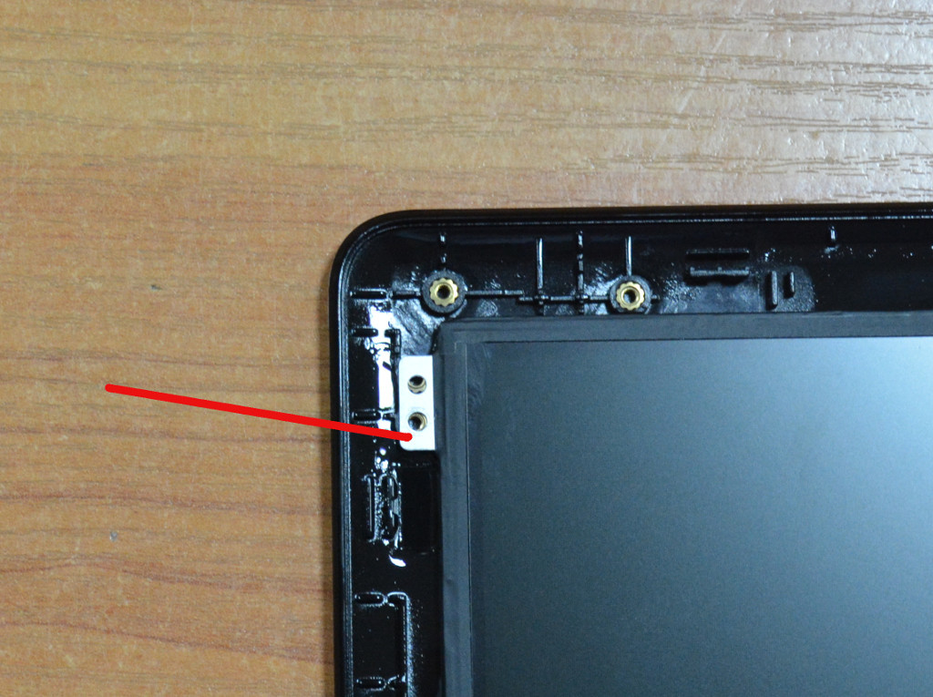
Then fix the upper corners with M2 x 3 mm screws like this:
Now place the TERES-020-Camera-Lens above the camera sensor and rubber mats over the two screws:
Now assemble the LCD part with the keyboard body. Use 6 screws M2 x 4 mm for this purpose:
Note that there are four places on the hinges but only three get assembled with screws. The fourth hole should be left empty; the extra screw will come from the bottom plastic body attachment. The places where you have to put screws are stamped at the metal hinges with arrows.
Next connect the WiFi antenna cable and LCD cable to TERES-PCB1-A64:
Battery
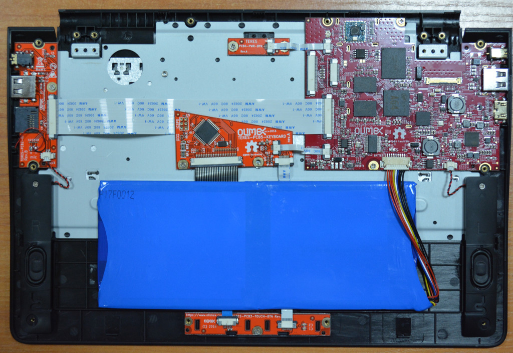
The next step is to attach four double adhesive mats that would hold the LiPo battery in place:
Attach the battery and plug the battery connector to the PCB1. Mind the orientation of the cable and polarity! Red cables should go to the left side.
Final Steps
Next put the TERES-021-Dust-Protectors at the openings of the bottom plastic TERES-005-Bottom:
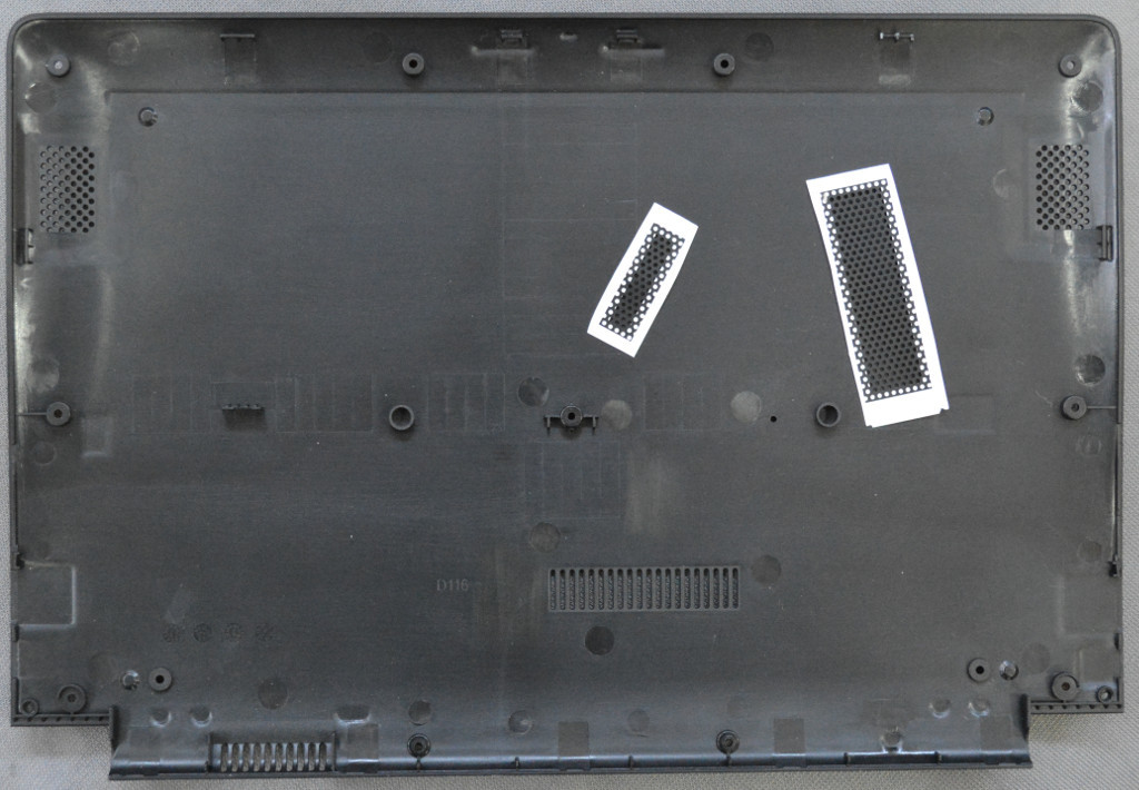
In the next image, you see the dust covers placed over the two openings:
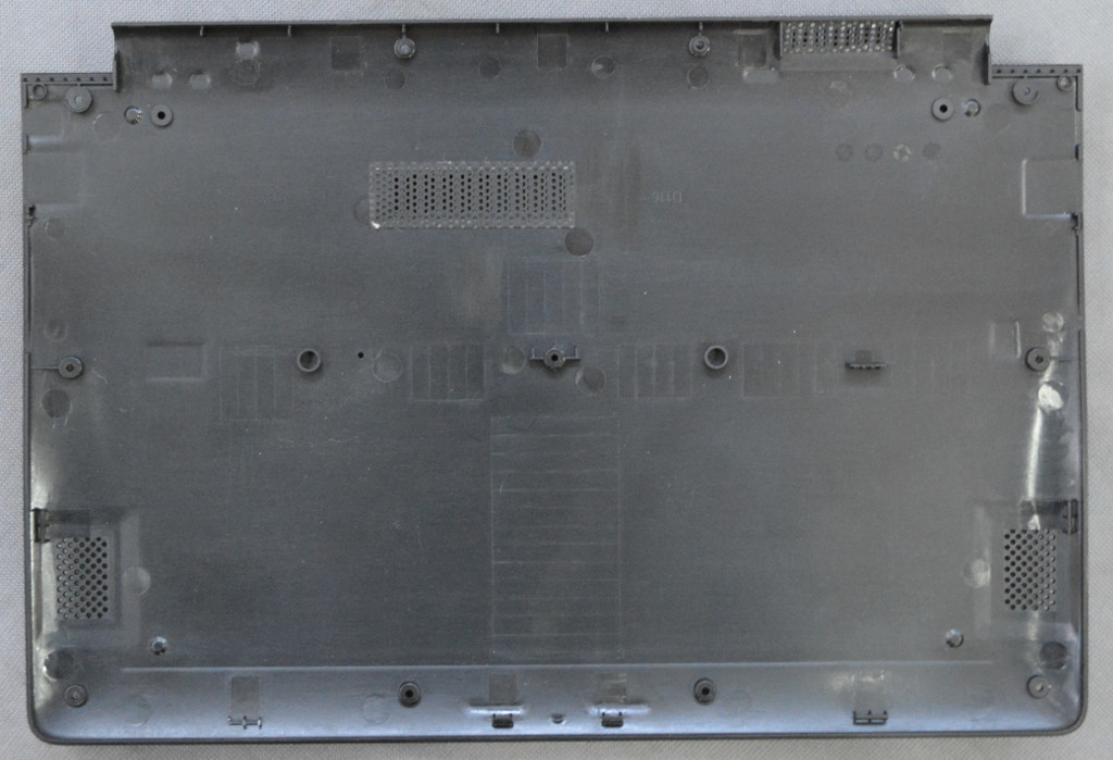
Next assemble the bottom plastic using 12 M2 x 5 screws:
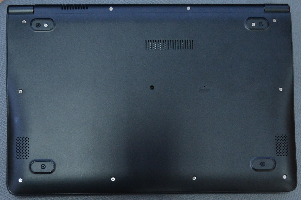
The final step is to attach the rubber mats to the four locations at the bottom:

The assembly is now complete. Now press the power button and the laptop will boot:

Congratulations! You assembled your TERES-I laptop!