* /README.md derived from https://www.olimex.com/Products/DIY-Laptop/

* Moved DOCS/ to doc/ standard

* Added TERES-A64-{BLACK,WHITE} images for docs

* Added link to DIY kit purchase page

* Add OLIMEX logo

* Added images to /README.md; minor text revision

* Moved TERES-I odt+pdf to doc/manuals/

* Create index.rst

This file allows public documentation to be compiled and hosted at sites such as <proj>.readthedocs.io

* Partial commit of web-based TERES-I manual

* Added links from guide (index.rst) to /README.md

* Added link to d/l manuals; fixed link typos

* Fixed image links

* Mis-labeled image title

* Fixed image path

* Changed to HTML for image size control

* Added facebook+twitter svg light icons

* Relinked facebook+twitter to light svg icons

* Adding github+wordpress svg icons

* Relinked to github+wordpress svg icons

* Made icons into links; still have size issues

* Added 50x50px icons

* 50x50 pixel icons to addres sizing issue

* Initial table of contents for DIY kit

* Added kit inventory images

* Remove duplicate image

* Premature commit because my computer keeps crashing and losing my data

* Iterative commit of docs as to be cautious

* Another iterative commit

* Last iterative commit for assembly walkthrough

* Need a ! in front of images for them to appear
2.2 KiB
Introduction to the hardware of TERES-I
The TERES-I electronics part consists of five boards. Each board was designed with KiCad open source CAD software. You may download KiCad* and open for reviewing or editing each of the PCB files. The schematics are also available as PDF exports for easier viewing.
NOTE: Make sure to download the latest KiCad nightly development build. The latest stable build may not have the features required.
The MAIN board (PCB1-A64-MAIN) contains:
- A64 processor
- RAM and flash NAND memories
- Power management unit
- LCD converter
- Connectors to different interfaces
- and others
It looks like this:
We expect to release extra main boards with different processors and memory configurations in the future. These should work with all other existing boards. It is expected newer main boards to have higher laptop speed and improved memory performance.
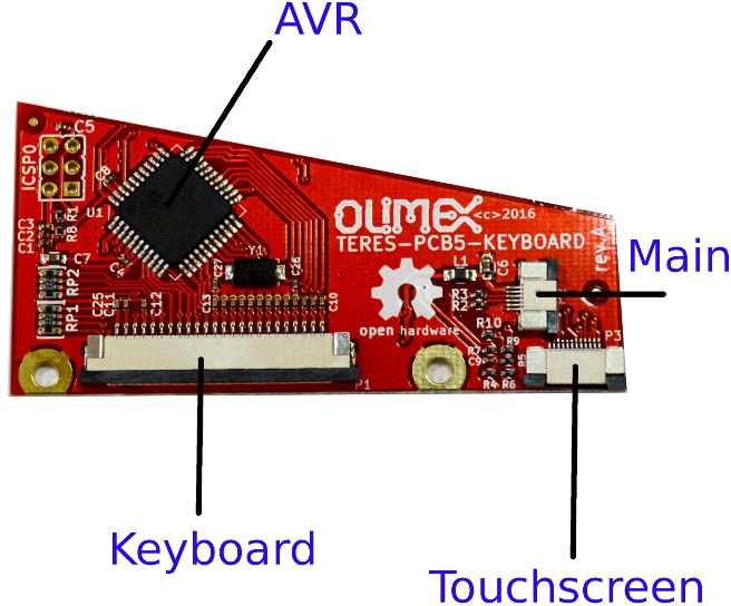
The KEYBOARD controller board (TERES-PCB5-KEYBOARD) has an AVR processor. You can update the firmware of the keyboard/touch controller live on the board itself. It can also be programmed via an Arduino microcontroller. This board is responsible for handling the keyboard and touch pad interfaces.
Sources, binaries and update procedures for the AVR firmware are available at GitHub. This keyboard controller board allows you to completely reprogram the keyboard mapping and response according to your own taste. The touch screen parameters can also be changed.
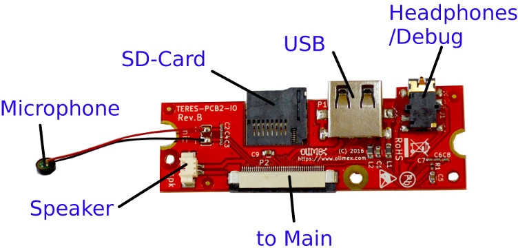
The IO board (TERES-PCB2-IO) contains the USB connector, headphone/debug connector, SD card, speaker connector and microphone.
The PWR button board (PCB4-PWR-BTN) handles the keys for powering on and off the laptop.
The TOUCH buttons board (TERES-PCB3-TOUCH-BTN) contains two buttons for left and right mouse click emulation.


